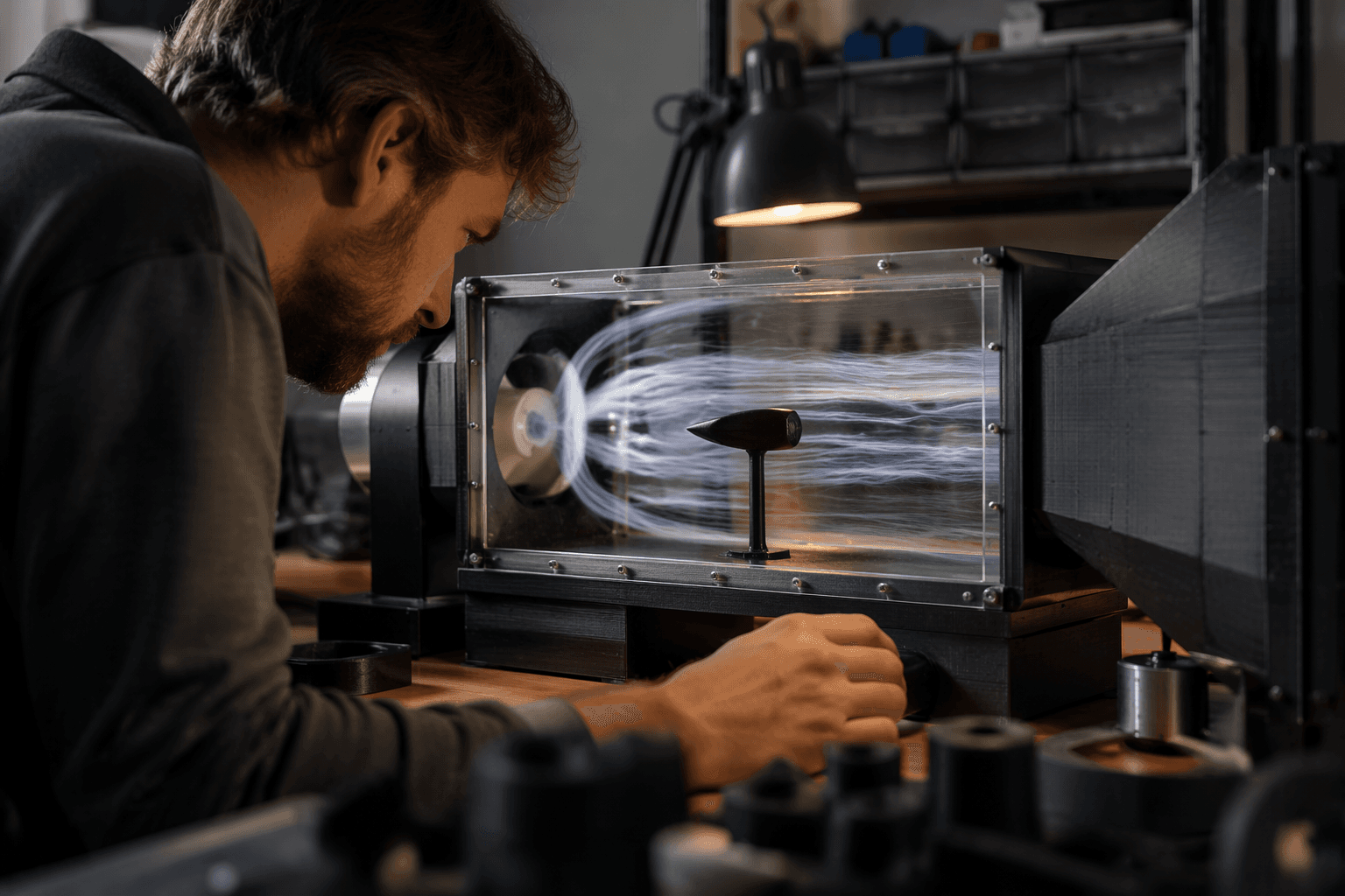
3D printable desktop wind tunnel makes airflow visible at home
A desktop wind tunnel can expose bad duct geometry, dead zones, and turbulence before you waste filament. The trick is building just enough flow control to trust the pattern, not the absolute numbers.

A desk-sized tunnel gives you something slicers never can: a live read on airflow
If you print RC ducts, fan shrouds, drone parts, or cosplay shells that still have to move through air cleanly, a desktop wind tunnel gives you an immediate sanity check. You can watch smoke or another visual tracer bend around a profile, spot where flow separates, and compare one printed shape against another before you commit to a full-size part. That is the real payoff here: not a lab-grade answer, but a fast way to see whether a design is helping or hurting.
The best part is that you do not need a huge shop setup to make the test useful. A printed enclosure, a fan, a straightening section, and a simple part mount already give you a workable platform for checking drag, lift tendencies, and turbulence around a model. For hobby work, that is often enough to save a reel of filament and a night of guesswork.
What a desktop tunnel can tell you, and what it cannot
A small wind tunnel is excellent for comparing shapes. You can test hole patterns, leading edges, duct lips, curved versus sharp transitions, and surface changes that affect how air attaches or breaks away. If a shroud looks smoother in the tunnel and the smoke stays tighter across the surface, you have a practical reason to keep that geometry.
It also helps with parts that live in moving air all the time. That includes RC airframes, cooling ducts, prop guards, mounting fairings, and decorative shells that still have to behave in the real world. The tunnel will not replace full-scale aerodynamic testing, and it will not give you universal drag numbers you can apply to every size or speed. Think of it as a relative test bed: useful for direction, not final certification.
That distinction matters because airflow is sensitive to scale. A shape that behaves one way at desk scale may behave differently on a full-size part, especially if the fan output is uneven or the test section is too short. The closer you get to clean, repeatable flow, the more trust you can put in the pattern you see.
The minimum build that makes the setup worth using
You can keep the structure simple and still get real value from it. The parts that matter most are the ones that make the air consistent and the test repeatable:
- A rigid tunnel body with a clear test section
- A fan or blower that can run at steady speed
- A flow straightener, such as a honeycomb or screen section
- A mount that holds the test part in the same spot every time
- A way to visualize flow, usually smoke or a similar tracer
Once those pieces are in place, the tunnel becomes more than a novelty. The enclosure and fixtures can be customized around whatever fan, sensor, or model you want to use, which is exactly why 3D printing fits the job so well. You can resize the test chamber, swap mounts, or reprint a new insert for a different part instead of rebuilding the whole rig.
If you want to move beyond visual impressions, add measurement hardware only after the flow itself is readable. That keeps the project practical. A load cell, for example, can help quantify lift, but only after the tunnel is stable enough that the numbers mean something.
Why makers keep returning to this old aerodynamic idea
Wind tunnels have been central to aerodynamics for a very long time. Benjamin Robins used a whirling-arm device in 1746 to study air resistance, and George Cayley later used a whirling arm in the early 1800s to measure drag and lift on airfoils. NASA notes that wind tunnel design has evolved for more than a century, from hypersonic facilities with test sections only inches across to the 80-by-120-foot section at the National Full-Scale Aerodynamics Complex.
That history is exactly why a desktop version feels so satisfying. The core idea has not changed. You still push air past a shape, watch what happens, and learn how geometry changes performance. What has changed is access: the hardware is now cheap enough and printable enough that a home builder can reproduce the basic experiment without booking time in a major lab.
NASA’s 2025 reference work, *Wind Tunnels of the NACA and NASA*, underlines that long arc. The scale is wildly different, but the lesson is the same: once airflow becomes visible, design decisions get much easier to defend.
Recent printed builds show how practical the format has become
The maker community has already turned this into a useful pattern. MakerWorld’s Modular Wind Tunnel for STEM Education was described as a functional, interactive, modular low-speed tunnel built entirely around FDM/FFF printing, and it later won first place in MakerWorld’s Physics Education contest. Its creator said the project was meant to get more kids excited about STEM, and it was made free on January 21, 2025 to widen use in homes, classrooms, and makerspaces.
A University of Surrey student took a similar approach with a 3D-printed portable wind tunnel after finding that the university’s own tunnels were hard to access because of heavy demand. That build was aimed at an RC airplane module where students had to design, test, make, and evaluate their own aircraft. In other words, the tunnel was not just a cool side project. It solved a bottleneck in the workflow.
Team Jeju M-Tech at Jeju National University pushed the same idea into an open-source kit. Their low-cost, fully 3D-printable wind tunnel includes honeycomb and screens for flow quality control, supports a beam load cell and Arduino lift measurement, and was validated against NACA 0012 experimental data at Reynolds number around 48,000. That last detail matters because it shows the concept can move beyond classroom spectacle and into repeatable aerodynamics work.
The real value for home builders
For you, the attraction is not that a desktop tunnel mimics a research facility. It is that it gives you a fast, visible way to test a printed part before you waste material on the wrong shape. If you are tuning a duct, a shroud, or a prop fairing, the first useful answer is often the simplest one: does the airflow stay attached, or does it fall apart the moment it meets your geometry?
That is where this kind of build earns its keep. It turns the invisible into something you can see on a desk, and once you can see it, the next print has a much better chance of working.
This article was produced by Prism’s automated news system from verified source data, official records, and press releases, then run through automated quality and moderation checks before publishing. The system is built and supervised by the people who set the standards it runs under. Read our full AI policy.
Did this article answer your question?