DCC Layout Wiring Guide Covers Installation, Testing, and Troubleshooting Steps
Bad DCC wiring kills decoders and stalls trains — here's the exact wire gauge, feeder spacing, power district logic, and quarter-test protocol that separates a reliable layout from a frustrating one.

Bad wiring is the root cause of most DCC problems. Stalling locomotives, erratic decoder behavior, mysterious short-circuit shutdowns — in the vast majority of cases, the track and infrastructure doing the electrical work simply aren't up to the demands of digital command control. DCC boosters can output five to eight or more amps, and that power needs a clean, low-resistance path from command station to rail. What worked fine under old-school DC block control will fail under DCC.
This guide covers the full chain: wire selection, bus and feeder installation, power district design, reverse loop handling, testing procedures, and the troubleshooting steps that isolate the real problem fast. It applies equally to a fresh build and to a DC-to-DCC conversion.
Wire Gauge: Get This Wrong and Nothing Else Matters
When converting to DCC, the first and most important thing on the list is verifying that the wiring is capable of handling the increased power capacity. Light gauge wire is simply not up to the task.
The standard rule of thumb for HO is 14-gauge solid core wire for the main bus up to 100 feet, with 24-gauge stranded wire for the short feeder wires that drop from the bus to the track. In practice, most experienced builders land on 14 AWG for the main bus and 18 to 22 AWG for feeders, with the exact choice depending on run length and booster amperage. AWG 14 or heavier is not overkill for a power bus, and track feeders of AWG 18 are not that heavy. Choosing wire because it is cheaper or easier to hide is only asking for problems.
At the 5-amp maximum typical of most indoor DCC layouts, 14 gauge is fine, and 16 gauge will work for smaller layouts. For very long runs or higher-amperage supplies, heavier wiring like 12 gauge may be a good idea.
For insulation, stranded wire is preferred over solid wire because it is more flexible to work with and less likely to break connections. Always use stranded wire; it's more flexible and easier to work with than solid wire, and will last longer in places where it does have to flex. One exception: it's common to use thinner solid wire for feeders because it's easier to work with and easier to solder to the outside of the rails.
Building the Power Bus
Regardless of what DCC system you use, you will be better off installing a proper DCC power bus. A DCC power bus is typically designed as a parallel wiring system rather than a continuous ring, to minimize the risk of short circuits, voltage drop, and to facilitate easier installation and troubleshooting.
For larger layouts, run a main bus wire under the layout with feeder wires connecting to the track every few feet to ensure consistent power and signal. The NMRA recommends running feeder wires from every three-foot section of flex track. Run feeder wires from each three-foot section of flex track. Smaller sections or pieces of track should also have jumper wires run to each rail from the previous three-foot section, so long as it does not connect two zones or power boosters. Doing this ensures good continuity throughout the rails over the entire layout.
Color coding the bus pair is a practical investment from day one. You can use the same color wire throughout if you wish, but using different colors will aid any fault-finding at a later date.
There is ongoing discussion about whether to twist bus wires together. Keeping sub-bus wires as close together as possible reduces the inductance of the bus, which can help maintain DCC signal integrity and reduce the energy of voltage spikes from shorts. A twist every foot or so is sufficient.
Feeder Connections: Solder or Suitcase?
There are three standard methods for connecting feeders to the bus:
1. Strip the insulation from the house wire at regular intervals and solder the feeder directly. Quick and inexpensive, but rework is difficult.
2. Slip-on connectors like Scotchlok will slide over large-gauge wire and connect it to smaller-gauge wire. They are quick but somewhat expensive and more prone to failure than soldered connections.
3. Mount a barrier terminal strip every so often under your mainline and at both ends of major yards. This is the most serviceable long-term option for club layouts.
Whatever method you choose at the bus, solder the connection at the rail itself. Some people like to solder all connectors. That's a good idea for things that are hard to reach and won't ever need to be changed, like feeder wires where they connect to the track. A smooth, shiny joint is the target. Solder guns are not recommended because they are too hard to control the heat. Use a pencil iron.
After soldering, use insulating tape or heat shrink tubing to insulate and protect connections and wires from short circuits. And label everything: wire labels or markers help identify wires and connections, especially in larger layouts.
Power Districts and Circuit Breakers
Consider dividing the layout into power districts using circuit breakers to isolate sections and prevent a short circuit in one area from affecting the entire layout. This is not optional on any layout where you intend to run multiple trains reliably. If a train derails in one zone on the layout and shorts out, tripping that power booster's circuit breaker, the trains on other zones keep running.
The Digitrax PM42's trip current threshold can be set between 1.5 amps and 12 amps. Always use the lowest possible setting consistent with good operation and reliable short-circuit detection and recovery. Setting breakers too high defeats their purpose and risks cooking decoders.
The data or control bus should be run as far as is practical away from the track bus. Where power and control buses have to cross, they should ideally do so at right angles.
Reverse Loops and Wyes
Every reverse loop and wye needs both rails gapped at each end of the section. To wire reversing loops, both rails must be gapped at each end of the loop. A double-throw/double-pole toggle can be used, or you can purchase a separate automatic reversing card such as the DCC Specialties PSXAR reversing units.
Reversers work by detecting short circuits, the same way a DCC circuit breaker does. If a reverser is connected downstream from a circuit breaker, the reverser needs to be set to detect the short at a lower current than the circuit breaker is set to trip at; otherwise the circuit breaker will simply shut off all the track power to the reversing section.
Converting from DC: What to Check First
When converting to DCC, the first and most important thing is verifying that the wiring is capable of handling the increased power capacity. Light gauge wire is not up to the task. As a rule of thumb, the main source of power to the track should be at least 14 AWG.
Many older layouts were wired in stages using a variety of wires and techniques, with many splices and connections. This can make troubleshooting difficult, and if doing an upgrade, replacing the wiring is probably a better option. Sloppy wiring and poor wiring practices can lead to poor operations, burnt-out decoders, short circuits causing damage, and even runaway locomotives.
To avoid possible expensive damage to your decoders and DCC system, wire your layout so that it is not possible to have DC power and DCC power present on the layout at the same time.
Booster phasing is another conversion-specific hazard. Phasing is very important if you are going to use multiple boosters. Both should be connected to the track in the same manner. To verify, a simple DMM on the AC volts range will suffice: place one probe on either side of the gap and read the voltage. It should be zero. If you see voltage, the boosters are out of phase.
Testing: The Coin Test and Voltage Under Load
The final test to carry out before moving on is the coin test. Place a coin across the live rails, creating a short, and see whether your command station shuts the power off. If it does, all is well. If it does not cut power, you have to trace the wiring to find the reason why. When carrying out the coin test, make sure you have only the controller connected and no locos standing on any tracks, as damage may be caused.
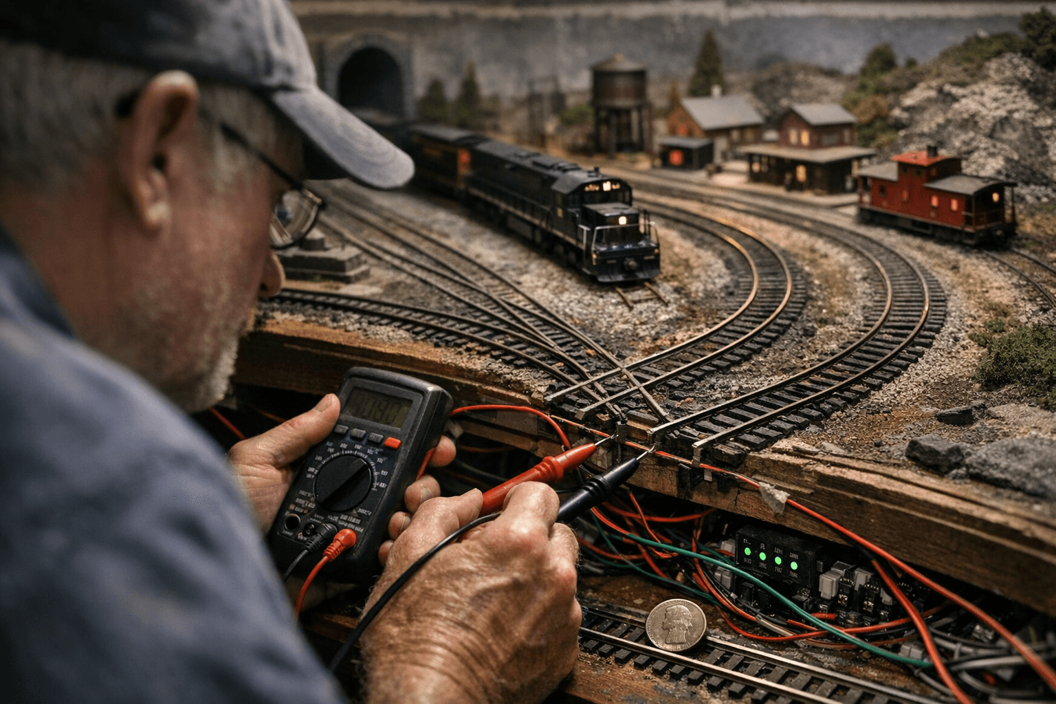
Voltage testing under no-load conditions tells you almost nothing. If there are no loads on the rails, the voltage can look fine, but under load, the voltage can drop if you have bad connections, poor wiring, or a bad transformer. Therefore you need a way to put a load on the rails and, while the load is applied, measure the voltage in various spots. If the voltage is low, you have a bad connection or wire. This low voltage is called voltage drop.
For best performance, the bus size in AWG shall be such that there is no more than a 5% voltage loss at the furthest point from the power station at the maximum current of the power station. Exceed that and decoders start behaving erratically.
Troubleshooting Common Problems
Common issues include loose wire connections, short circuits, and incorrect wiring. Work through them systematically:
- Inspect the layout's wiring to identify and fix any loose connections, damaged wires, or problematic solder joints. Securely fasten all connectors and check for shorts or crossed wires that might cause electrical issues.
- DCC systems can be sensitive to signal interference from sources including fluorescent lights, wireless routers, and other electronic devices. If you notice erratic behavior, try to isolate and eliminate potential sources of interference. Relocating or shielding your DCC command station and boosters can help minimize signal disruptions.
- If you're encountering issues with a specific section of your layout, isolate it for testing. Disconnect the problem area from the rest of the layout and connect it to a separate DCC system if available. This will help you determine if the problem is isolated to that specific area.
- Consider adding signal boosters to your layout, especially if it's large or has complex trackwork. Boosters can help maintain a strong DCC signal across the layout, reducing the likelihood of stalling or signal loss.
The single most preventable problem on any DCC layout is under-gauged wire on a bus that was originally built for DC. Voltage drop is important as a safety matter because the booster must be able to fully drive its rated current for the overload protection to trip. Too much voltage drop may limit the drive current of the booster during a short condition, leading to excessive heat buildup and damage to equipment. Spec the wire correctly from the start, solder every rail joint, test under load, and the layout will reward the effort every operating session.
Know something we missed? Have a correction or additional information?
Submit a Tip