3D Printed Front Panels Can Generate Their Own Precise Drill Guides
A 0.5 mm UV-resin layer printed directly onto plywood gives every hole its own self-centering donut and a clean-edge collar, eliminating jigs and post-drilling cleanup entirely.

Misaligned knob holes. Ragged edges around LED cutouts. The connector that lands 2 mm to the left of where it should because your hand-held drill drifted the moment the bit touched wood. If you have ever built an instrument panel, audio enclosure, or gaming cabinet without a drill press or laser cutter, you have met every one of these problems. A maker named [bluesyann] has now documented a technique that removes them all at once, and the key to the whole thing is a layer of UV resin just 0.5 mm thick.
The method, highlighted by Hackaday, rethinks what an MSLA resin printer is actually doing. Rather than building an object on its standard build plate, [bluesyann]'s approach replaces that plate entirely with a sheet of plywood. Sanded smooth and attached to the build platform with double-sided tape, the plywood positions itself within the printer's UV exposure zone. Some setups may require an alternative build plate mount to keep the plywood-plus-platform combination within the printer's Z-axis travel limits, but the adjustment is minor. Once in place, the printer cures resin directly onto the wood surface. Because the plywood absorbs a small amount of resin during exposure, the printed features bond cleanly without any adhesive beyond what the curing process itself provides.
The result is a front panel with faintly raised linework bonded to its surface, ready to drill, with no separate jig required.
Designing the Guide Layer: Inkscape to OpenSCAD
The workflow begins in Inkscape, and the software's 1:1 dimensional fidelity is one of its most useful properties for this kind of work. A 10 mm circle in the layout produces a 10 mm feature on the physical panel, which means every component footprint, every connector cutout, and every mounting hole translates directly from screen to wood without conversion arithmetic.
Once the layout is complete, OpenSCAD imports the .svg file and extrudes it into a 3D solid at a height of exactly 0.5 mm. That specific depth is deliberate: thin enough to remain visually subtle and not interfere with panel hardware clearances, but substantial enough to create the tactile drill-guide features that make the method work. This 0.5 mm model loads into the MSLA printer, with the plywood taking the place of the build surface, and the printer does the rest.
The Two Features That Fix Drilling Accuracy
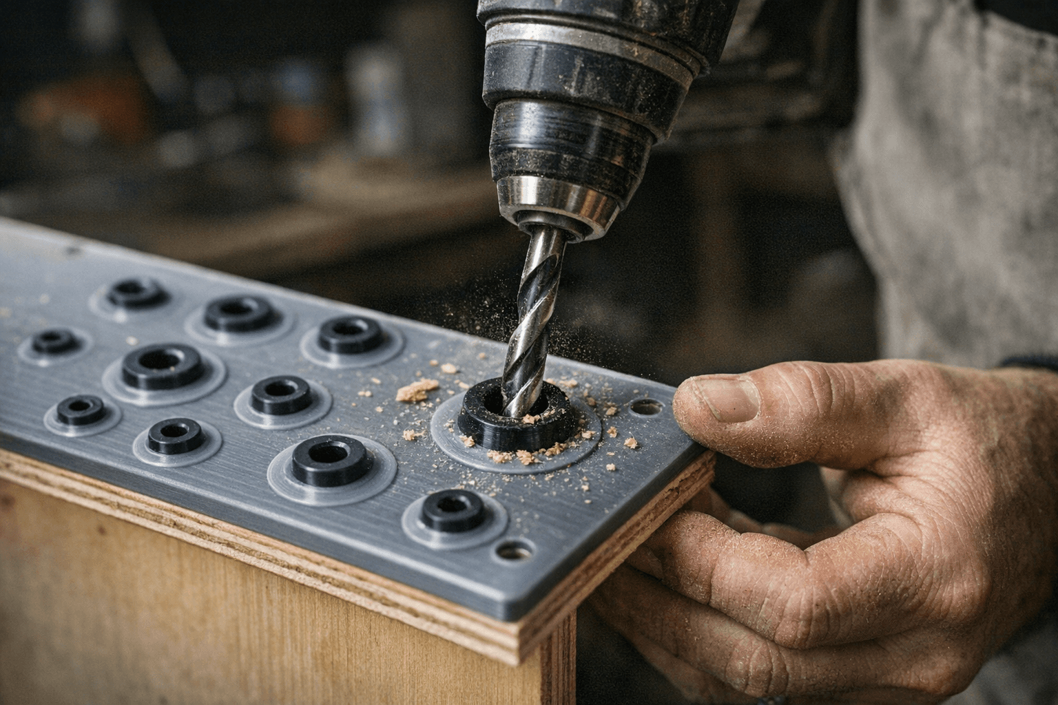
Two specific geometry choices in [bluesyann]'s design handle the hand-drilling accuracy problem directly, and both are embedded in that same 0.5 mm layer.
The first is a small donut shape centered on every hole position. Seat the tip of your drill bit in the donut and it self-locates, removing the drift that causes off-target holes when working by eye. The second is a thick surrounding ring that encircles the full diameter of the intended hole. During drilling, this collar contains any wood fiber tear-out and delivers a clean, finished edge with no post-drilling cleanup required. If you want a flush surface after assembly, the ring peels off once the hole is drilled. No residue, no sanding, no chasing ragged fibers with a craft knife.
Cleanup for the rest of the cured panel is a straightforward soak in isopropyl alcohol followed by a scrub with an old toothbrush to remove any uncured resin.
Caveats and Material Choices for FDM Builders
For makers who want to build removable drill guides using FDM rather than curing resin onto the panel directly, Hackaday recommends PETG or PLA+ as the filament of choice. Both materials provide the rigidity needed to resist deflection when a drill bit makes contact. A slightly snug fit between the printed guide and the panel prevents movement during drilling, and adding a light chamfer to each guide hole eases the bit into position without catching.
Large-diameter holes deserve extra attention regardless of the method used. Progressive drilling with pilot holes prevents the cracking and chipping that can occur when a large bit is driven through a resin-printed panel in a single aggressive pass. Skipping the pilot hole step is a reliable way to ruin an otherwise finished piece.
Alternative Finishing Techniques
For setups where resin printing is not available, two alternatives produce professional results using common equipment. Laminating printed artwork directly onto an enclosure surface is one proven route. Toner transfer onto 3D printed surfaces is another: with FDM printing, the heat of molten plastic deposited on top of toner-printed paper is enough to bond the design to the surface directly. For wood substrates specifically, heat-assisted toner transfer delivers solid bond quality and a clean surface finish without requiring any specialized materials.
A Process That Changes What a Panel Is
What [bluesyann]'s approach establishes is that a front panel does not have to be a passive cosmetic layer you drill through and hope for the best. At 0.5 mm thick and built with free software that any Inkscape and OpenSCAD user can access, the guide layer carries the precision of your CAD layout directly to the contact point between drill bit and material. The gap between home-shop results and the kind of clean panel work that usually demands a laser cutter or CNC machine just got considerably narrower.
This article was produced by Prism’s automated news system from verified source data, official records, and press releases, then run through automated quality and moderation checks before publishing. The system is built and supervised by the people who set the standards it runs under. Read our full AI policy.
Did this article answer your question?