3D Printed PLA Patterns Enable Backyard Cast Iron Metal Parts
Your FDM printer is already a metal foundry pattern maker: a PLA print, fine silica sand, and a microwave-heated silicon carbide crucible can yield a cast iron adjustable wrench for a fraction of the cost of any metal 3D printing service.
Cast iron costs pennies per gram when you melt scrap. LPBF printers cost between €500,000 and €1.5 million. That gap is exactly where this workflow lives, and it is smaller than you might think to bridge, provided your FDM machine is already running.
Denny, the maker behind the YouTube channel Shake the Future, documented the full sequence from CAD file to finished cast iron adjustable wrench, and Hackaday covered it in detail. The process threads together three mature but rarely combined techniques: FDM patterning, sand mold making, and microwave-susceptor metal melting. None of them individually is exotic, but the combination opens a door that most desktop-printer owners have never considered walking through.
Why Not Just Order Metal Prints?
The honest answer is cost and lead time. Bureau metal printing services charge a significant premium per part, and even the most affordable sintering-based desktop metal systems sit well above what most hobby budgets can justify. More importantly, those services and machines impose their own design constraints: support removal, powder management, and post-sintering shrinkage all demand engineering attention. The sand-casting workflow described here trades some of those headaches for a different set, but at a capital outlay that amounts to consumable molding sand, a bag of PLA, and a purpose-built silicon carbide crucible that Denny fabricates himself.
For parts where grade-A metallurgy is not the requirement, such as custom brackets, tool handles, props, or replacement hardware, the functional strength of cast iron or cast aluminum is more than adequate. The process also preserves something metal printing cannot easily match: the ability to iterate a pattern in PLA within hours, test the mold geometry, and reprint a corrected version the same afternoon before committing to metal.
The Core Workflow, Step by Step
The sequence Denny demonstrates follows classical lost-pattern sand casting, updated with two modern shortcuts.
1. CAD and print the pattern. Design every component in standard CAD software and print in PLA.
For the adjustable wrench, this means four separate pieces: the handle, the movable jaw, the knurled adjustment wheel, and the holding pin. These are positive models, not molds.
2. Pack the sand mold. Using fine silica sand mixed with a sodium silicate binder, pack the mold tightly around each printed part.
Sodium silicate lets the mold be hardened without a traditional oven-cure clay system. Denny cures his molds through a combination of freezing, oven heating, and low-power microwave treatment, making the mold rigid enough to hold the cavity geometry once the pattern is removed or burned away.
3. Burn out the PLA. Firing the packed mold drives off the plastic, leaving a clean negative imprint of the part geometry in sand.
This burnout stage is where thin-walled features become a liability: the PLA expands before it melts, and if the surrounding sand wall is too thin, it can crack or shift. Denny's first attempt produced failures specifically at the thin-walled regions around fastener seats, which is an instructive design lesson rather than a project-ending setback.
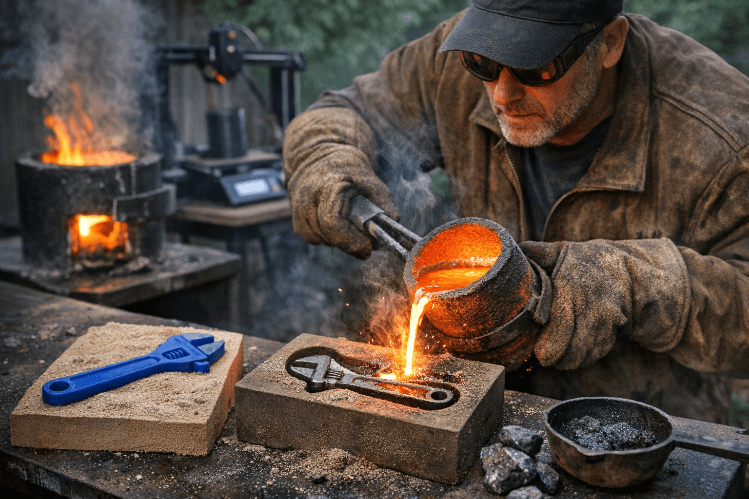
4. Melt and pour. The silicon carbide crucible is the key piece of equipment.
Silicon carbide is a microwave-susceptor material: it absorbs microwave radiation and converts it directly into heat. Placed inside an insulated container with scrap iron loaded on top, the crucible reaches the temperatures needed to achieve melt without a dedicated gas forge or induction system. Once molten, the metal is poured into the sand cavity through a gating system.
5. Break out and finish. The sand mold is broken apart, the casting is cleaned, and the individual pieces are assembled into a working adjustable wrench.
Mold Design Rules That Actually Matter
The burnout failure on the first attempt is the most instructive moment in the entire project, because it maps directly onto the DFM (design for manufacturability) rules that any foundry engineer would give you on day one.
- Fillet every internal corner. Sharp re-entrant angles concentrate stress in the sand wall during burnout and during the thermal shock of the pour. A radius of even 1.5-2mm buys significant reliability.
- Eliminate or redesign thin cross-sections. Features thinner than roughly 3mm in cast iron are high-risk: they cool too fast, invite misrun defects, and the PLA pattern itself may crack the surrounding sand during expansion. Redesign thin features as gusseted sections or accept that they will need post-cast machining.
- Avoid complex undercuts in the pull direction. Sand molds require a clean parting line. Undercuts that prevent the pattern from releasing cleanly from the sand either demand a multi-part mold with cores or must be redesigned out of the pattern geometry. FDM's ability to print overhangs does not translate to freedom in the mold.
- Design your gating and riser system. The metal needs a path in (the gate), and the mold needs a path for trapped gas and displaced air to escape (vents). A riser, an extra reservoir of molten metal above the casting, compensates for shrinkage as the iron solidifies. Skipping the riser is one of the most common causes of a porous, weak casting.
The Microwave Crucible: Clever, But Respect Its Limits
The silicon carbide crucible trick is genuinely elegant for small-volume melts. It eliminates the need for a propane forge or induction heater, both of which represent significant equipment investments and require their own safety infrastructure. But "low capital" does not mean "low risk," and Denny's documentation is explicit on this point.
Molten cast iron runs above 1,200°C. At that temperature, any moisture in the mold causes an instantaneous steam explosion. The insulated container holding the crucible must be stable and never placed on a surface that could allow tipping. Full PPE is non-negotiable: a face shield rated for molten metal splash, leather foundry gloves, and leather or denim covering all skin. A leather apron is standard practice, not optional theater. Ventilation matters too, both during the PLA burnout (which produces combustion gases) and during the pour itself.
The critical advice Denny and Hackaday's coverage converge on: do not start with cast iron. Aluminum melts at around 660°C, is far more forgiving of equipment variation and mold moisture, and gives you the reps needed to understand gating, mold packing density, and pour speed before you commit to a material whose failure modes are more severe. Most local maker spaces that run metalcasting programs begin their members on aluminum for exactly this reason, and connecting with one before attempting a solo first pour is strongly recommended.
The Real Cost-and-Capability Comparison
What does this workflow actually deliver versus the alternatives?
Versus a metal printing service: A cast iron part made this way costs little more than the weight of scrap metal and the sand consumed, plus time. Bureau LPBF or binder-jetting services typically price small parts in the range of tens to hundreds of dollars depending on geometry and material, with lead times of days to weeks. The casting route is slower per-part on the first iteration because mold design takes real work, but once the mold system is dialed in, repeat pours are fast and cheap.
Versus buying a desktop metal printer: Entry-level sintering-based metal printers still cost thousands of dollars and require proprietary feedstock. The casting setup described here has a materially lower entry cost, though it demands more active skill.
Finish and tolerances: Sand casting produces a rougher surface than LPBF or sintering. Tolerances are in the ±0.5-1mm range for a competently made sand mold, which is fine for brackets, tool bodies, and decorative hardware but not for precision-fit mechanical interfaces without post-machining. LPBF can hold tolerances an order of magnitude tighter, with smoother as-printed surfaces.
Iteration speed: This is where the PLA pattern approach genuinely shines. Reprinting a modified pattern takes hours. Adjusting a CNC-machined metal pattern takes days and money. For early-stage geometry exploration, FDM patterning is legitimately faster than any alternative short of wax injection.
What Parts Are Actually Appropriate?
The honest use case for this workflow is functional parts where dimensional precision matters less than strength and durability, and where the geometry is complex enough to make CNC machining expensive or slow. Custom clamps, machine handles, housing brackets, period-correct hardware for restoration projects, and one-off tools are all well-suited. High-tolerance bearing seats, threaded interfaces, or any part subject to fatigue cycling in a safety-critical assembly are not, at least not without machining to final dimension after casting.
The adjustable wrench Denny chose as his demonstration piece is deliberately instructive: it is complex enough to illustrate the mold design challenges (multiple moving parts, different cross-section thicknesses, an adjustable mechanism) while being exactly the kind of tool where "good enough metallurgy" is, in fact, good enough.
Every FDM printer in every shop is already capable of producing a casting pattern. The question is whether the mold design work and the foundry skills are worth acquiring for your specific project needs. For anyone who has priced out a custom metal bracket from a bureau service recently, this workflow is worth a serious look.
This article was produced by Prism’s automated news system from verified source data, official records, and press releases, then run through automated quality and moderation checks before publishing. The system is built and supervised by the people who set the standards it runs under. Read our full AI policy.
Did this article answer your question?