Designing Better Screw Holes, How to Make 3D Prints Functionally Stronger
One bad screw hole can wreck a near-finished print. The fix is in the geometry: clearances, wall thickness, layer direction, and the right fastener strategy.

The screw hole is where good prints go to die
You know the moment. The part looks clean, the dimensions seem right, and then a screw bites in too hard, cracks the wall, and turns a promising print into scrap. Hackaday’s guide puts that failure exactly where it belongs: not on the screw, but on the hole, the layers around it, and the way the part was asked to flex in the first place.
That matters because screws are still one of the most common ways to turn a printed object into something useful. They hold repair brackets together, close custom enclosures, and make machine parts serviceable after they leave the printer. In that context, screw-hole design is not a tiny detail. It is the difference between a part that assembles once and a part that survives repeated use.
Hole size is only the starting point
The easiest mistake is to treat hole diameter like a single number you can copy from an old slicer profile and forget. In practice, the hole has to work with shrinkage, over-extrusion, and the way plastic behaves when a screw starts cutting or compressing into it. Makelab notes that holes in 3D printed parts tend to come out slightly smaller than designed because of shrinkage and over-extrusion, which means a CAD model that looks perfect on screen may feel tight in real life.
Makelab’s current guidance gives a useful baseline: a minimum hole diameter of 2.0 mm for FDM and SLA, and 1.5 mm for MJF. It also recommends adding 0.1 to 0.2 mm to the radius for FDM holes and 0.05 to 0.1 mm for SLA holes to compensate for the way those processes close in on the final feature. Those numbers are not magic, but they do replace guesswork with a repeatable starting point.
Just as important, orientation changes the shape of the hole. Makelab says vertically oriented holes, printed along the Z-axis, are more accurate and round than horizontal ones. That is why a hole that seems fine in CAD can print oval, undersized, or rough enough to make screw insertion miserable once it is laid on its side.
The wall around the hole matters as much as the hole itself
A screw does not only press on the diameter of the opening. It also pushes outward on the material surrounding it, and that surrounding structure has to carry the load. Hackaday’s guide emphasizes the relationship between the screw, the layer orientation, the thickness around the hole, and the way the plastic deforms under insertion pressure. That is the part many makers miss when they rely only on nominal diameter.
If the perimeters around the hole are thin, the wall can split before the screw is fully seated. If the layer direction is wrong, the screw can exploit the weakest plane in the print and pry it apart. UltiMaker’s support guidance adds another reason to think structurally: some engineering materials shrink more than others, which can warp or distort features and hurt print reliability even when the model looked sound in CAD.
- Add enough perimeter and local wall thickness around fastener points.
- Keep holes away from edges and thin ribs.
- Treat layer orientation as a structural choice, not just a visual one.
- Test the fit on a small sample before committing to a full batch.
For functional parts, the fix is often simple:
This is why the best screw-hole advice rarely starts with the screw itself. It starts with the part geometry around it.
Choose the fastening method before you choose the hole
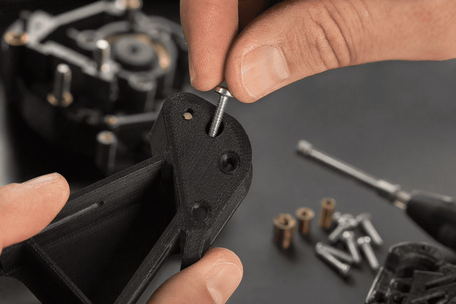
Formlabs points out that there are several ways to attach screws to 3D printed parts, including inserts, tapping, and even printed threads. That range matters because not every hole should be used the same way. If the part needs frequent assembly and disassembly, a bare printed thread can become a wear item very quickly. If the hole only needs to hold once, a simpler approach may be enough.
Heat-set inserts are often the safest option when a part has to be opened and closed repeatedly. UltiMaker says they are commonly made of brass and come in sizes such as M3 and M5. It also notes that they are much less prone to stripping and deforming than threads that are printed or tapped directly into plastic parts. In real-world use, that means better pull-out resistance and better torque resistance, which is exactly what you want when a screwdriver slips or a fastener gets over-tightened.
The design rule that follows is straightforward: if the joint has to survive service, do not force the plastic to act like metal. Build the part around an insert.
When to use printed threads, and when not to
Printed threads are tempting because they feel elegant. They eliminate extra hardware and can look neat in a model. But they are the wrong choice when the fastener will see repeated use, higher torque, or any situation where stripping would be a problem.
- The load is light.
- The part will not be opened often.
- The geometry gives the thread enough engagement depth.
- You can accept wear over time.
Use printed threads only when:
- The screw will be removed and reinstalled repeatedly.
- The fastening point is thin or close to an edge.
- The joint needs real torque resistance.
- The part lives in a vehicle, machine, or other demanding assembly.
Skip printed threads when:
UltiMaker’s emphasis on vehicles and factory machinery is a useful reminder here. 3D printed parts are not just desk toys anymore. Once they go into equipment that gets serviced, vibrates, or carries load, the fastener strategy has to match the job.
A better workflow for CAD and print settings
The good news in Hackaday’s explainer is that you do not need a different printer to get better results. You need a more disciplined process. Think of the screw hole as a designed feature, not an afterthought.
A practical workflow looks like this: 1. Decide whether the joint needs a screw, a tapped hole, a printed thread, or a heat-set insert. 2. Size the hole with a compensation value, not just the nominal screw diameter. 3. Print vertically when possible so the hole stays round and accurate. 4. Give the surrounding wall enough thickness, especially if you are using inserts. 5. Watch for shrinkage and over-extrusion in your slicer profile. 6. Test fit on a small part before trusting a full build.
For heat-set inserts, Makelab recommends wall thickness around the insert of at least 2 times the insert diameter. That is a useful floor, because the insert needs enough plastic around it to stay anchored without splitting or softening the part into a failure point. In other words, the insert should strengthen the joint, not become the thing that fractures the shell.
Why this tiny feature keeps deciding whether prints feel real
The larger lesson here is the one functional makers already know by instinct: a part is only as good as the details that let it be assembled, repaired, and used again. A screw hole is a small feature, but it sits at the intersection of CAD, slicing, layer direction, material behavior, and mechanical load. That is why a hole can look perfect and still fail the moment a screw enters it.
Hackaday’s guide lands in the right place because it replaces folklore with design practice. Build the hole with shrinkage in mind, orient it for accuracy, give it enough wall behind it, and choose the right fastening method for the job. That is how a print stops being merely finished and starts becoming dependable.
This article was produced by Prism’s automated news system from verified source data, official records, and press releases, then run through automated quality and moderation checks before publishing. The system is built and supervised by the people who set the standards it runs under. Read our full AI policy.
Did this article answer your question?