Study maps 3D printer speed to vibration frequencies
A new study ties toolhead speed to vibration frequencies, showing why ringing appears when acceleration gets greedy on sharp corners.
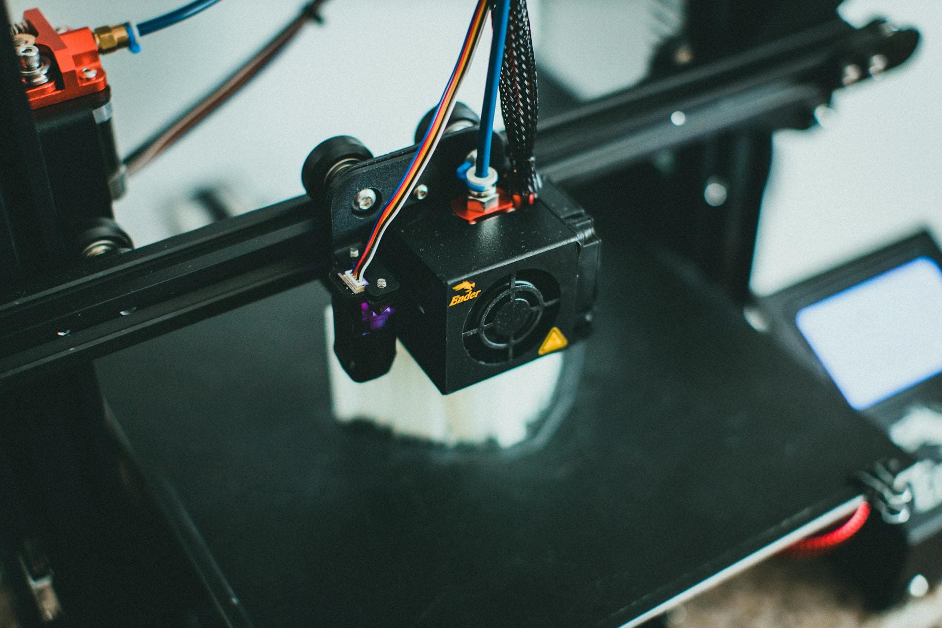
Push a desktop FDM printer too hard, and the first warning is often visible on the part itself: ripples on corners, ringing on edges, and ghosting that can ruin an otherwise clean print. A new open-access paper, A Verifiable Steady-State Frequency-velocity Mapping for Desktop FDM Printers Based on an Electromechanical Coupling Framework, tries to make that failure mode less mysterious by linking commanded speed directly to the vibration frequencies a machine excites.
The study, published in Machines on May 2, 2026, was written by Xinfeng Zou, Haiyan Miao, Baoshan Huang, Zhen Li, and Fengshou Gu, with affiliations at the University of Huddersfield in the United Kingdom and Guangdong Mechanical & Electrical Polytechnic in China. Rather than asking only what resonance frequency a printer has, the authors asked what speed is triggering a given frequency. That is the more useful question for anyone trying to squeeze more throughput out of a desktop rig without turning surface quality into a washboard.
Their electromechanical coupling framework traces the chain from stepper actuation through the transmission system to machine motion, then maps that motion to a steady-state frequency-velocity relationship. In one test case, the researchers used two constant printing-velocity segments, 40 mm/s and 80 mm/s. When the commanded speed doubled, the dominant frequency changed by roughly the same factor, which is exactly the kind of relationship that matters when a slicer profile starts to cross into ringing territory.
Validation came on an experiment platform with an accelerometer mounted on the x-axis beam near the motor end. In steady segments and toolpath directions, the relative error between measured and theoretical drive frequency stayed below 3%, a tight enough match to suggest the map can predict where vibration starts to bite before it shows up as ugly banding on the print. The practical takeaway is straightforward: once a toolpath lands in a speed range that lines up with the machine’s vibration pattern, pushing acceleration higher can stop helping and start harming the finish.
That lines up with the guidance already baked into Klipper and Prusa’s tuning docs. Klipper describes ringing, also called echoing, ghosting, or rippling, as a result of quick changes in direction, and points to loose or springy belts, poor alignment, insufficient frame rigidity, and heavy moving mass as common causes. Its input shaping system is an open-loop control method that depends on tuning and measurements, usually with a ringing test model. Prusa says its Input Shaper is designed to reduce ghosting by canceling resonance vibrations, and lists support across newer printers including the MK4, MINI/+, XL, CORE One family, MK4S, MK3.9/S, and MK3.5/S, with rollout starting in firmware 5.0.0 for the MK4 and 5.1.0 for the MINI/+ and XL.
A 2025 MDPI study pushed the same idea even further, reporting that Klipper plus systematic calibration and additional hardware or software could cut print time by up to 50% while maintaining dimensional accuracy and improving surface quality. That is the real promise here: not brute-force speed, but knowing the resonance ceiling well enough to print faster without making every corner pay the price.
This article was produced by Prism’s automated news system from verified source data, official records, and press releases, then run through automated quality and moderation checks before publishing. The system is built and supervised by the people who set the standards it runs under. Read our full AI policy.
Did this article answer your question?