Why 3D prints fit poorly: accuracy, precision and tolerance explained
A printer can repeat the wrong size perfectly. Here’s how to separate accuracy, precision, and tolerance so hinges, gears, and boxes finally move.
When a box looks perfect in CAD but the lid still binds, the problem usually is not the model. It is the gap between the digital dimension you drew and the real dimension your printer can hold, repeat, and mate.
That is where accuracy, precision, and tolerance stop being lab terms and start being the difference between a free-spinning hinge and a fused one. A printer’s “high resolution” spec does not mean the finished part will be accurate or precise.
Accuracy is how close the part lands to the target
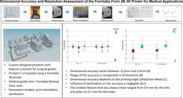
Accuracy is the easiest of the three to picture. If you modeled a 20 mm peg and the printed peg comes out 19.7 mm, that part is not accurate, even if every copy is the same. Formlabs published a Form 3 dimensional accuracy report in May 2021 that tested parts across two size ranges, from 1 mm to 50 mm and from 60 mm to 130 mm, because dimensional behavior changes with size.
A tiny latch tab, a medium bracket, and a longer enclosure wall do not all drift in the same way, so a printer that seems reliable on one part can still miss on another. Dimensional behavior has to be evaluated across size ranges, not just from the marketing spec sheet.
Precision is whether the printer repeats itself
Precision is about repeatability, not correctness. A machine can be very precise and still produce the wrong size every time, which is exactly why two identical printed parts may fit each other better than they fit the nominal CAD dimension. In hobby terms, the printer is saying, “I always make this peg 0.2 mm small,” and then doing that faithfully.
If every print is off by the same amount, you can compensate in CAD or in the slicer. If the output changes from part to part, the issue is usually deeper in the machine setup, the material behavior, or the build conditions.
Tolerance is the gap you design on purpose
Tolerance is not what the printer “achieves” on its own. It is the allowed difference between mating parts, the margin that lets a peg enter a hole, a gear turn freely, or a cover close without sanding. In the practical world of printed parts, tolerance is the number that decides whether a design assembles at all.
A Prusa forum answer treats one extrusion width as the basic unit of accuracy, with a default of 0.45 mm for a 0.4 mm nozzle. That is not a universal magic number, but it is a good reminder that the nozzle and extrusion width set the scale of the problem before the model ever hits the bed.
Why the process matters before you touch the model
FDM, SLA, and SLS do not fail in the same way, so they do not want the same clearance. FDM parts often show shrinkage, elephant’s foot on the first layers, and anisotropic behavior because layer stacking affects both surface finish and strength. That means a flat wall may look fine while a hole, boss, or snap-fit post behaves differently.
SLA gives you crisp detail, but resin parts bring their own complications. Resin continues to change dimension during and after post-curing, and Formlabs’ SLA printers use 405 nm lasers to cure the liquid resin. In other words, the part that comes off the build plate is not always the part you end up with after cure.
SLS is often the friendliest process for complex interlocking parts because unfused powder can support overhangs, but it brings rougher surface texture and its own dimensional drift. Process choice, material, and build conditions shape fit as much as the CAD file does.
The fastest way to find the real clearance
The cleanest habit in functional printing is to stop guessing and print test pieces. Measure them with calipers, compare the result to the CAD dimension, and keep a note of what the printer actually does with holes, slots, pegs, and walls. A calibration coupon is cheap insurance before you commit to a full enclosure or gear train.
A practical workflow looks like this:
1. Print a small test coupon with the same material, layer height, and orientation you plan to use.
2. Measure the critical features with calipers.
3. Compare the measured dimensions to the CAD values.
4. Adjust the model or slicer compensation only after you know whether the error is consistent.
5. Reprint the coupon before moving to the final assembly.
Holes, slots, bosses, and press-fit pegs rarely need the same compensation. A wall that comes out close to nominal does not guarantee a circular hole will do the same, and a peg that snaps into one material can be unusably tight in another.
Where the fix belongs: CAD, slicer, or printer
Once you know the error pattern, the fix usually points in one of three directions. If the same feature is off by the same amount every time, the correction often belongs in CAD or slicer compensation. If the error changes from print to print, it is more likely a printer calibration issue, a mechanical inconsistency, or a material problem.
Formlabs Dental says its Precision Model Resin for Form 4 can place more than 99% of printed surface area within 100 m of the digital model, which shows how tightly fit matters in restorative dental models. On the industrial side, Stratasys announced Accuracy Center and Thickness Analysis on January 9, 2024.
This article was produced by Prism’s automated news system from verified source data, official records, and press releases, then run through automated quality and moderation checks before publishing. The system is built and supervised by the people who set the standards it runs under. Read our full AI policy.
Did this article answer your question?